TM-9-2350-260-20-1-2 - Page 189 of 772
TM 9-2350-260-20-1-2
POWERPLANT LEFT BANK OIL COOLER FRAME AND BRACKETS REPLACEMENT (2D ENGINE) (Sheet 6 of 9)
INSTALLATION:
NOTE
Because of space limitations, it may be necessary to interchange like-size sockets
with wrenches to get at a particular screw.
1.
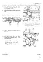
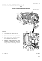
Install screw (A) through bracket (B).
2.
Position bracket (B) and screw (A) on engine.
3.
Install clamp (C) on screw (A).
4.
Using 9/16 inch socket and 9/16 inch wrench,
install new self-locking nut (D).
5.
Using 1/2 inch socket with extension, install new
self-locking nuts (E).
6.
Position bracket (F) on engine.
7.
Using 1/2 inch socket with extension, or 1/2 inch
wrench, install nuts (G).
8.
Position clamp (H) on fuel line and install screw (J)
through clamp (H) and bracket (F).
9.
Using 1/2 inch socket and 1/2 inch wrench, install
nut (K) on screw (J).
10.
Using 1/2 inch socket with extension, install four
brackets (L).
11.
Position frame support brackets (M) on engine
and, using 11/16 inch socket, install two new self-
locking nuts (N) to secure each frame support
bracket (M).
Go on to Sheet 7
TA147564
6-112
Back to Top


