TM-9-2350-260-20-1-3 - Page 480 of 783
TM 9-2350-260-20-1-3
SHIFTING CONTROL BRACKET AND CONNECTING LINK ASSEMBLY REPAIR
(Sheet 6 of 9)
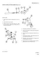
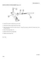
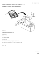
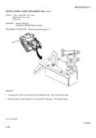
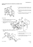
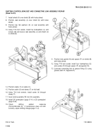
14. Place bracket (P) into vise.
15. Using 5/16 inch combination wrench, remove grease
fitting (Q.
16. Inspect grease fitting (Q) for blockage or damaged
threads.
Throw away if damaged.
17. Using 1/8 inch allen wrench and 7/16 inch wrench,
remove setscrew and jamnut (R).
18. Turn bracket (P) over, and using hammer and 1/2
inch punch, remove shaft (S).
19. Remove connecting link (T) spacer (U) and two
washes (V).
20. Inspect washes (V) and connecting link bearings
(W).
NOTE
If bearings (W) are to be replaced,
perform steps 21 and 22.
21. Using 1/2 inch punch and hammer, remove bearings (W).
22. Using vise, press new bearings (W) one at a time into
connecting link (T) flush with outer surface of connecting
link (T).
Go on to Sheet 7
TA146603
11-49
Back to Top

