TM-9-2350-260-20-1-3 - Page 512 of 783
TM 9-2350-260-20-1-3
FINAL DRIVE (LEFT AND RIGHT) REPLACEMENT (Sheet 4 of 4)
CAUTION
Do not damage threads on mounting
studs when installing studs through
mounting holes.
4.
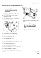
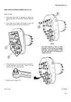
Carefully guide mounting studs through mounting
holes (D) in side of hull.
5.
Using lubricating oil (Item 44, Appendix D), oil 17
new self-locking nuts (E).
6.
Using fingers, start threads of 17 new self-locking
nuts (E) onto final drive studs (F).
7.
Using socket or offset link, install 17 new self-locking
nuts (E).
NOTE
Use hand impact wrench offset link
with torque wrench where torque
wrench cannot be used due to lack of
space.
8.
Using torque wrench, tighten 17 new self-locking
nuts (E) to 460-500 lb-ft (625-680 N
•
m).
9.
Remove hoist hook from final drive lifting eye.
10. Install hub and sprockets assembly (page 14-79).
11. Install track assembly (page 14-84).
12. Install rear outrigger (page 16-80).
13. Install rear fender stowage box (page 16-185).
14. Install rear fender handset box (right side only) (page 16-196).
15. Install adapter assembly (page 12-10).
16. Install rear powerplant guides (page 6-5).
17. Install 2A powerplant (page 5-14), or 2D powerplant (page 5-40).
18. Fill final drive with oil (Item 44, Appendix D).
19. Drive tank to perform operational check (TM 9-2350-260-10).
End of Task
TA146636
12-5
Back to Top

