TM-9-2350-261-20-2 - Page 171 of 1008
TM 9-2350-261-20-2
REPLACE REGULATOR ASSEMBLY (100/200 AMP GENERATOR) — Continued
0230 00
INSTALLATION
1.
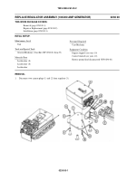
Place regulator (8) upside down and place four new lockwashers (2) on holes (3). Set mount plate (4) on regulator and
place four more new lockwashers (5) on holes (6). Secure mount plate to regulator with four screws (7).
NOTE
Ground lead is on 200 amp system only.
2.
Set regulator (8) and mount plate assembly (4) on hull weldnuts (9). Slide four new lockwashers (10) under mount plate
(4) on hull weldnuts. Place four new lockwashers (11) on mount plate over holes (12). Slide end of ground lead (13)
under lockwasher (11). Secure with four screws (14).
3.
Place other end of ground lead (13) on ground stud (15). Secure with new lockwasher (16) and nut (17).
4.
Connect two cannon plugs (18) and (19) to regulator (8).
FOLLOW-THROUGH STEPS
1.
Connect battery ground lead (WP 0294 00).
2.
Adjust regulator voltage (WP 0229 00).
END OF TASK
0230 00-3/4 blank
Back to Top


