TM-9-2350-261-20-2 - Page 161 of 1008
TM 9-2350-261-20-2
REPLACE GENERATOR AND ADJUSTMENT LINKAGE (200 AMP
GENERATOR ONLY) — Continued
0228 00
NOTE
It may be necessary to loosen two screws (20) and swing generator up to remove lower screws
(21) from generator mounting bracket.
8.
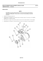
Support generator with wood block and remove two lower screws (21) and washers (22), from generator from mounting
bracket (23).
9.
Remove two upper screws (21), washers (22), and generator mounting bracket (23) from fuel filter bracket (24).
10. Remove generator (13) and attached mounting bracket (23) from power plant compartment. Have helper assist.
NOTE
If replacing generator, do Steps 11 - 15.
11. Remove three screws (25) that secure pulley (26) and bushing (27) to generator shaft (28).
12. Install three screws (25) in threaded holes in pulley (26). Tighten screws until bushing (27) separates from pulley.
13. Remove pulley (26) and bushing (27) from generator shaft (28).
14. Remove key (29) from generator shaft (28).
15. Remove two locknuts (30), washers (31), and screws (20) from generator (13) and mounting bracket (23). Remove
bracket from generator. Discard locknuts.
022800-3
Back to Top


