TM-9-2520-270-34 - Page 565 of 933
TM 9-2520-270-34
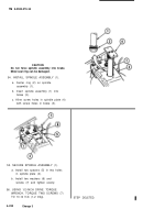
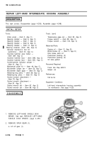
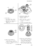
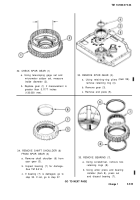
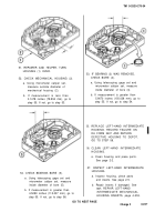
16. CHECK GEAR CLUSTER (1).
a. Using telescoping gage set and
micrometer caliper set, measure
diameter of hole (2).
b. Replace gear cluster (1) if measure-
ment is greater than 3.3778 inches
(85.796 mm), Go to step 21. If not,
go to step 17.
NOTE
Some gear clusters may have access
access holes are present, bearing
removed using drive punch from opposite side
of gear cluster.
holes. If
may be
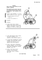
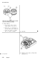
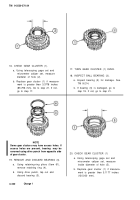
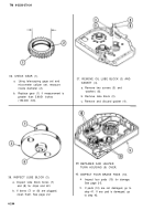
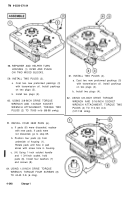
19. REMOVE AND DISCARD BEARING (3).
a.
b.
4-240
Using retaining-ring pliers (Item 61),
remove retaining ring (4).
Using drive punch, tap out and
discard bearing (3).
Change 1
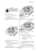
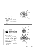
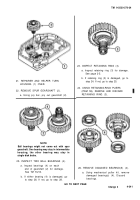
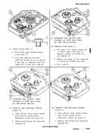
17. TURN GEAR CLUSTER (1) OVER.
18. INSPECT BALL BEARING (3).
a. Inspect bearing (3) for damage. See
TM 9-214.
b. If bearing (3) is damaged, go to
step 19. If not, go to step 21.
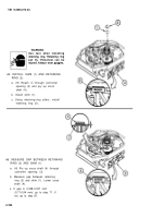
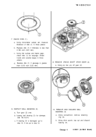
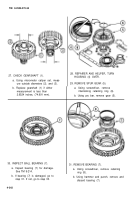
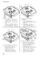
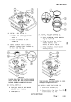
20. CHECK GEAR CLUSTER (1)
a. Using telescoping gage set and
micrometer caliper set, measure
inside diameter of hole (5).
b. Replace gear cluster (1) if measure-
ment is greater than 5.1177 inches
(130.000 mm).
Back to Top

