TM-9-2520-270-34 - Page 654 of 933
TM 9-2520-270-34
REPAIR LEFT-HAND OUTPUT HOUSIN G
DESCRIPTION
This task covers: Disassemble (page 4-323), Assemble (page 4-330).
INITIAL SETUP
Tools:
Crowfoot attachment – (Item 20, App C)
General mechanic’s tool kit:
automotive — (Item 33, App C)
Industrial goggles – (Item 39, App C)
Inserted hammer face holder —
(Item 39A, App C)
Inserted hammer face – (Item 39B, App C)
Inserted hammer face – (Item 39C, App C)
Inside/outside indicator caliper —
(Item 41, App C)
Micrometer caliper set – (Item 52, App C)
Retaining-ring pliers — (Item 60, App C)
Socket wrench adapter – (Item 75, App C)
Socket wrench attachment —
(Item 82, App C)
Socket wrench set – (Item 89, App C)
Telescoping gage set — (Item 93, App C)
Torque wrench — (Item 99, App C)
Torque wrench – (Item 100, App C)
Wire-twister pliers – (Item 107, App C)
Materials/Parts:
Lockwire — (Item 5, App B)
Sealant compound – (Item 11, App B)
Transmission oil — (Item 12, App B)
Cotter pin
Gasket
Lock washer (8)
Retaining ring
Special rubber seal
Personnel Required:
Track Veh Rep 63H10
Helper (H)
References:
TM 9-214
Equipment Conditions:
Left-hand output housing on workbench.
See page 4-314.
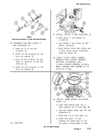
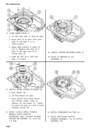
DISASSEMBLE
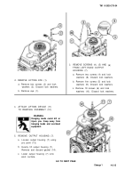
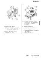
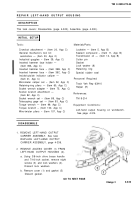
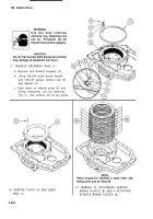
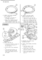
1. REMOVE LEFT-HAND OUTPUT
CARRIER ASSEMBLY. See task
REPLACE LEFT-HAND OUTPUT
CARRIER ASSEMBLY, page 4-336.
2.
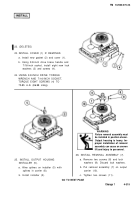
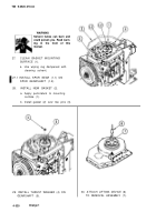
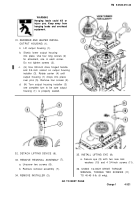
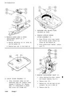
REMOVE ACCESS COVER (1) FROM
LEFT-HAND OUTPUT HOUSING (2).
a. Using 3/8-inch drive brace handle
and 7/16-inch socket, remove eight
screws (3) and lock washers (4).
Discard lock washers.
b. Remove cover (1) and gasket (5)
Discard gasket.
GO TO NEXT PAGE
Change 2
4-323
Back to Top

