TM-9-2520-270-34 - Page 655 of 933
TM 9-2520-270-34
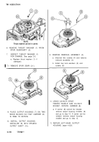
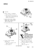
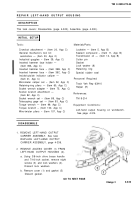
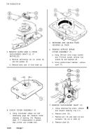
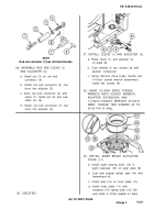
3. REMOVE LEVER ARM (1) FROM
SHOULDERED SHAFT (2), IF
INSTALLED.
a. Remove self-locking nut (3), screw (4),
and flat washer (5).
b. Remove lever arm (1) from shaft (2).
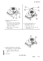
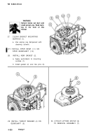
6. CHECK COVER ASSEMBLY (7).
a.
4-324
Using micrometer caliper set and
telescoping gage set, measure inside
diameter of bushing (10). Replace
plate (7) if measurement is greater
than 0.7513 inch (19.083 mm).
Change 1
4.
5.
REPAIRER AND HELPER TURN
HOUSING (6) OVER.
REMOVE SERVICE BRAKE
COVER ASSEMBLY (7).
a. Using 3/8-inch drive brace handle
and 7/16-inch socket, remove four
screws (8) and washers (9).
b. Using plastic-faced hammer, remove
cover (7).
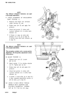
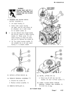
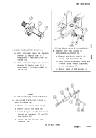
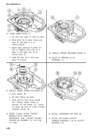
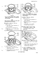
7. REMOVE SHOULDERED SHAFT (2).
a.
b.
c.
d.
Using retaining-ring pliers, remove
and discard retaining ring (11).
Remove shim (12).
Remove pin (13) and slide rod end
connector (14) out of shaft (2).
Remove shaft (2).
Back to Top

