TM-9-2520-270-34 - Page 663 of 933
TM 9-2520-270-34
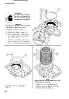
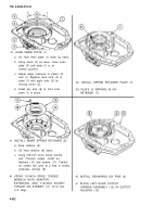
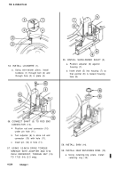
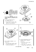
41. ALINE INNER PLATE (1).
a. (H) Hold inner plate (1) down by hand.
b. Using clevis (2) as lever, move outer
plate (3) until plate (1) is at
lowest position.
c. Helper apply pressure to plates (3)
and (1). Repairer aline slots (4) in
plate (1) with eight slots (5) by
moving clevis (2).
d. Install two pins (6) to hold inner
plate (1) in place.
44.
45.
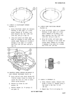
INSTALL INNER SPRING RETAINER (9).
a. Aline retainer (9).
b. (H) Hold retainer (9) down,
c. Using 3/8-inch drive brace handle
and 7/16-inch socket, install six
washers (10) and screws (11). Tighten
six screws two turns at a time to evenly
compress springs (8).
USING 1/2-lNCH DRIVE TORQUE
WRENCH WITH ADAPTER,
EXTENSION, AND 7/16-lNCH SOCKET,
TORQUE SIX SCREWS (11) 10-12 ft-lb
(1-2 mkg).
4-332
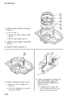
42. INSTALL SPRING RETAINER PLATE (7).
43. PLACE 10 SPRINGS (8) ON
RETAINER (7).
46.
47.
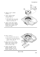
INSTALL REMAINING SIX PINS (6).
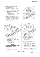
PLACE LEFT-HAND OUTPUT
CARRIER ASSEMBLY (12) IN OUTPUT
HOUSING (13).
Back to Top

