TM-9-2815-205-34 - Page 195 of 596
3-19. FUEL LINES REPLACEMENT (MODELS 5063-5395, 5063-5398, AND 5063-539F)
This task covers: a. Removal
b. Installation
INITIAL SETUP
MODELS
MATERIALS/PARTS
5063-5395 5063-5398 5063-539F
1
Lockwasher (App F, Item 99)
1
Lockwasher (App F, Item 97)
TOOLS AND SPECIAL TOOLS
Tool kit, general mechanics (App B, Item 107)
EQUIPMENT CONDITION
Wrench, torque (App B, Item 116)
Para Description
3-10 Air pump support removed
3-14 Coolant crossover tube removed
a. Removal
(1)
(2)
(3)
(4)
(5)
(6)
(7)
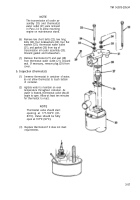
For models 5063-5395 and 5063-539F, remove screw (1), Iockwasher (2), flat washer (3), and
clip (4), on hose assembly (5), at rear of governor cover (6). Discard Iockwasher.
Disconnect hose assembly (5) from elbow (7) at rear of left cylinder head. Remove hose
assembly. If necessary, remove clip (4) from hose assembly.
Disconnect hose assembly (8) from elbow (9) in fuel pump (10). Remove hose assembly.
Disconnect hose assembly (11) from elbow (12) in fuel pump (10). Remove hose assembly.
Remove screw (13), Iockwasher (14), flat washer (15), and clip (16) on hose assembly (17) at
air inlet housing (18). Discard Iockwasher.
Disconnect hose assembly (17) from elbow (19) in front of right cylinder head. Remove hose
assembly. If necessary, remove clip (16) from hose assembly.
Loosen nut on two elbows (20) at front of cylinder heads and remove fuel crossover tube (21).
b. Installation
(1)
(2)
(3)
(4)
(5)
(6)
(7)
3-66
Connect hose assembly (11) to elbow (12) in inlet of fuel pump (10). Tighten hose connection.
Connect hose assembly (8) to elbow (9) in outlet of fuel pump (10). Tighten hose connection.
Connect hose assembly (5) to elbow (7) in fuel inlet of left cylinder head. Tighten hose
connection.
For models 5063-5395 and 5063-539F: if removed, install clip (4) on hose assembly (5). Install
clip, flat washer (3), Iockwasher (2), and screw (1) on rear of governor cover (6). Torque screw
to 7-9 Ib-ft (10-12 N
.
m).
Slide fuel crossover tube (21) into two elbows (20) at front of cylinder heads. Tighten nut on
each elbow.
Connect right fuel inlet hose assembly (17) to elbow (19) in front of right cylinder head. Tighten
hose connection.
If removed, install clip (16) on hose assembly (17). Install clip, flat washer (15), Iockwasher
(14), and screw (13) on air inlet housing (18). Torque screw to 16-20 Ib-ft (22-27 N.m).
TM 9-2815-205-34
Back to Top


