TM-9-2815-205-34 - Page 48 of 596
(4)
(5)
(6)
(7)
TM 9-2815-205-34
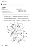
For all except models 5063-5393 and 5063-539L, slide hose (7) and two hose clamps (6). on
coolant pump (8), onto water by-pass tube (9). Tighten clamps securely.
Install two drive belts (5) on left camshaft pulley (16) and coolant pump pulley (17).
Install idler pulley assembly (4), two flat washers (3), two Iockwashers (2), and two screws (1)
If necessary, connect the fuel line, routed across the front of the coolant pump, to the fuel
junction block (refer to Para 2-5).
c. Adjustment
Loosen two screws (1) on idler pulley assembly (4).
Pry upward on tang of idler pulley
assembly (4) to get 1/4 to 3/8 inch
deflection on drive belts (5) midway
between pulleys (16 and 17) while
applying a firm push with thumb. Tighten
two screws (1).
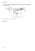
Check for proper tension by using straight
edge (18) to measure deflection across
drive belts at pulleys (16 and 17). If
tension meter is available, check for 40-50
Ibs (173-217 N) tension, If necessary,
readjust tension, and then torque two
screws to 30-35 Ib-ft (41-47 N•m).
END OF TASK
FOLLOW-ON MAINTENANCE
Para Description
2-4 Install water by-pass hose (models 5063-5393 and 5063-539L)
Change 1
2-21
Back to Top


