TM-9-2815-210-34-2-2 - Page 306 of 968
TM 9-2815-210-34-2-2
d .
Assembly.
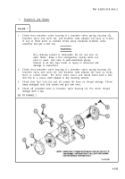
FRAME 1
1.
2.
3.
4.
5.
6.
GO
NOTE
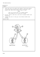
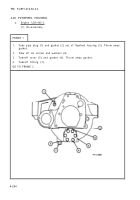
One of five holes (1) in diaphragm (2) and one of
five screw holes (3) in crankcase breather valve
housing (4) are offset.
Diaphragm can be put on
valve housing only one way.
Line up five holes (1) in new diaphragm (2) with five screw holes (3) in crank-
case breather valve housing (4). Note which side of diaphragm must face out
so that holes will line up.
NOTE
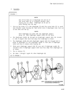
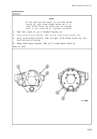
Each diaphragm (2) comes with two diaphragm support
disks (5).
Both diaphragm support disks are the same.
Put diaphragm needle (6) through one diaphragm support disk (5). Curved-
in side of support disk must face away from diaphragm as shown.
Put diaphragm needle (6) with diaphragm support disk (5) through hole in
center of diaphragm (2). Put diaphragm needle in from side of diaphragm
which will face in toward valve housing (4).
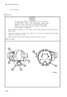
Slide outer diaphragm support disk (5) over end of diaphragm needle (6).
Curved-in side of diaphragm support disk must face away from diaphragm (2)
as shown.
Put on locknut (7).
Do steps 1 through 5 again for other diaphragm (8).
TO FRAME 2
4-287
Back to Top

