TM-9-2815-213-34 - Page 63 of 192
*TM 9-2815-213-34
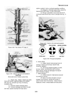
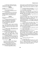
at each of remaining positions shown above (16 and
6.0 BTC).
If push rod travel is greater or le than
limits shown, timing is slow or fast respectively.
A
new camshaft key must be installed bring push rod
travel within limits.
Refer to paragraph 212.k.
for
removal of shaft, and pal graph 3-30 for disassembly.
NOTE
Before installing new key, make sure
guide spring on tappet body is not hold-
ing tappet off camshaft lobe.
i.
Recheck limits as outlined in Chart 3-1.
j.
Remove timing fixture and injector push rod.
Section XV.
Repair of Rocker Arm Assembly and Push Rods
3-80.
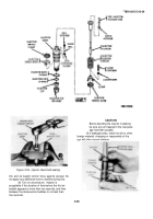
Disassembly
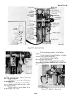
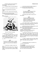
(fig.
B-6)
a.
Remove locating socket head stew
(44)
from mounting bracket (8).
The rocker shaft locating
socket head screws are located on rear left bank and
front of right bank assemblies.
b.
Slide rocker arm shaft brackets and rock
arms (47, 50, and 52) from the shaft (46).
c.
Remove rocker arm shaft plugs (45) from
each end of each shaft.
d.
Remove adjusting screws (55) and
locknut
(54) from rocker arms.
3.81.
Cleaning
Clean all parts in accordance with paragraph 2
3-82.
Inspection
a.
Rocker Arm Assembly
(1) Perform general inspection of rocker arm
assembly in accordance with paragraph 2-8
(2) Gage rocker lever bushings with tele
scope gage and micrometer.
(a) Set telescopic gage 0.0002 inch above
worn limit of 1.1905 inches for use as a plug gage.
NOTE
The inside diameter of a new rocker arm
bushing is 1.1875/1.1895 inches and may
wear to 1.1905 inches maximum.
(b) Replace bushings worn beyond limits
(para.
d, below).
(3) Check intake and exhaust rocker arm
crosshead contact surface.
If worn or damaged,
replace with new rocker arm.
(4) The ball end of rocker arm adjusting
screws must be true spheres.
Test with 1/4 inch
radius gage and replace worn adjusting screw
(5) Worn injector rocker arm sockets must
be replaced.
Wear is easily detected with fillet
gage or by observation of small protrusion at the
bottom of socket.
(6) Check that all lubricating oil passages
are open.
(7) Inspect thread condition on all screws and rocker
arms.
Check closely for thread dam- age at assembled
position of locknut.
Ensure
that screws operate freely through rocker arms.
(8) Check rocker arm shaft for scoring, galling, out-
of-round and wear.
If worn smaller than 1.1845 inches,
install new shaft.
NOTE
New rocker arm shaft measures 1.1856/
1.1865 inches with a wear limit to 1.1845
inches,
(9) Examine rocker arm shaft brackets for cracks,
breaks and stripped threads.
Replace as necessary.
(10) Visually inspect arm side surfaces which mate
with adjacent arms.
If galled, grind surfaces to original
smoothness.
b.
Push Rods.
(1) Check ball end of all push rods for worn radii.
A
new allowance of 0.3150 inch.
Check in- jector and valve
push rod ball ends with 5/16 inch radius gage.
(2) Test sockets of push rods with ball end of a new
rocker lever adjusting screw or with 1/4 inch fillet gage.
(3) Replace defective push rods.
Extreme wear on
either end of push rod will result in loss of lubricating oil
pressure and may interfere with proper injector and valve
adjustment.
3-83.
Repair
Repair of the rocker arm assembly and push rods is limited
to replacement of defective parts.
Re- place rocker arm
bushing as follows:
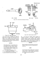
a.
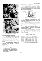
Press out worn bushing with mandrel and
block set (4, fig.
B-28).
3-34
Back to Top

