TM-9-2815-213-34 - Page 53 of 192
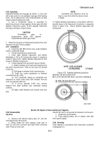
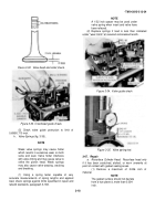
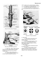
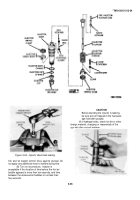
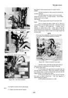
Figure 3-49.
Fuel injector PT (type C)
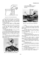
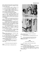
Figure 3-50.
Injector cup-removal/installation.
CAUTION
Never alter size of injector spray holes.
a.
Injector Cup
.
Inspect
injector cup spray
holes and tip with magnifying glass and compare
with new cup.
Discard cup if any of following
conditions exist:
(1
) Interior/or exterior abrasive wear.
(2
) Corrosion damage and effect of exces-
sive heat, usually resulting from high acid or
*TM 9-2815-213-34
sulphur content in fuel or overload operating conditions.
(3
) Enlarged or distorted spray holes, caused by
cleaning with drills, wires, or other instruments.
(4
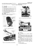
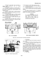
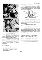
) Plunger seat pattern covers less than 40 %
continuous area around cup, cone or plunger bore (fig.
3-
52).
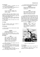
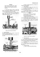
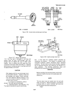
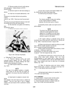
Figure 3-51.
Injector Link-removal/installation.
Figure 3-52.
Plunger seat pattern.
b.
Injector Body.
(1
) Inspect injector body plunger bore for
scoring, if scores are too deep, injector body
should be replaced.
(2
) Use strong magnifying glass to check
for burs, carbon, and distorted radii in orifices.
When injector orifices are damaged, the injector
will not function properly.
c.
Injector Plunger.
(1
) Check closely for metal seizure caused
by scuffing or scoring.
(2
) Spots or surface disruption at top of
plunger or at mid-point, usually are normal re-
sults of rocker lever thrust action.
Unless metal is
displaced or wear is measureable at these points,
3-24
Back to Top

