TM-9-2815-213-34 - Page 51 of 192
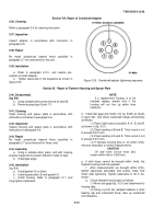
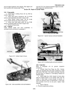
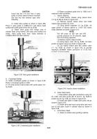
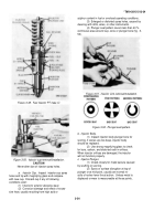
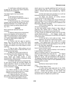
Figure 3-45.
Intake valve port swirl plate-installation
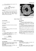
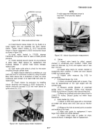
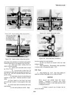
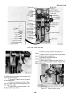
Figure 3-46. Valve seat insert peening.
(2
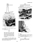
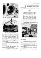
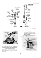
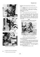
) Valve and seats must be dry and clean.
Place suction cup over valve head.
O-Ring on cup
should seat on flat surface of head surrounding
valve.
Grease area lightly with GAA for a better seal.
(3
) Turn
hand shut-off valve to open
position. Hold push button down to operate vacuum
pump.
(4
) Operate vacuum pump until hand on
vacuum gage stops climbing at 15/25 inches of
mercury on the dial.
(5
) Close shut-off valve; release push button
to stop pump.
(6
) Time vacuum pressure decrease on
gage
to test valve seat.
(
a
) "Start" timing as soon as hand
reaches "15" inches of mercury on dial.
(
b
) "Stop" timing when hand reaches
"12" inches of mercury on dial, if elapsed time
*TM 9-2815-213-34
is less than "10" seconds valve seat is unsatis- factory.
(7)
If valve seat seal is unsatisfactory:
(
a
)
Check for leaking connections on tester.
(
b
)
Operate tester with suction cup against
clean glass plate.
(
c
) Check for dirt on valve and seat.
(8
) If necessary regrind valve seat (para.
3-
68.e.).
NOTE
It is possible to mistake leakage around the
valve seat insert for valve seat leakage.
If
this is suspected, apply grease to the
outside edge of the insert to make a grease
seal.
Perform vacuum test and insert grease
seal for a "break" indicating air leakage
between wall of counterbore and valve seat
insert.
If leak around insert is detected,
correction is required before continuing with
test
b.
Head Assembly
.
Perform a water test on the
rebuilt head assembly (para.
366.c.).
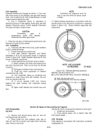
Figure 3-47.
Valve seat test.
3-70.
Installation
a
.
Make certain pipe plugs are installed and
secure.
b
.
Clean mating surfaces of cylinder block and
cylinder heads.
Make certain cylinder walls are
clean and well lubricated with OE-10 engine oil.
c
.
Place grommet retainers in water passages
in block, small end up.
d
.
Lay gasket on flat surface.
Press grommets
in place by hand.
e
.
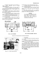
Install head gaskets over ring dowels so that
3-22
Back to Top

