TM-9-2815-213-34 - Page 41 of 192
•TM 9-2815-213-34
Section VIII. Repair of Crankshaft Adapter
3-36. Cleaning
Refer to paragraph 2-5 for cleaning instruction
3-37. Inspection
Inspect adapter in accordance with instruction in
paragraph 2-6.
3-38. Repair
No repair procedures beyond those specified in
paragraph 2-7 are authorized for this part.
3-39. Installation
a.
Refer to paragraph 2-1ll.i., and reverse pro-
cedures to install adapter.
b.
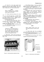
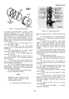
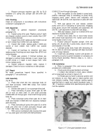
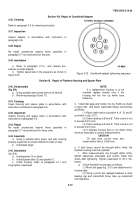
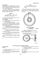
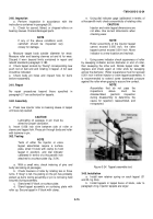
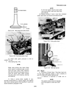
Tighten capscrews in the sequence as shown in
figure 3-20.
Figure 3-20.
Crankshaft adapter tightening sequence
Section IX.
Repair of Flywheel Housing and Spacer Plate
3-40. Disassembly
(fig. B4)
a.
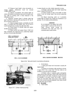
Using suitable arbor press remove oil seal (8).
b.
Remove pipe plugs (6 and 17).
3-41. Cleaning
Clean housing and spacer plate in accordance with
instructions contained in paragraph 2-6
3-42. Inspection
Inspect housing and spacer plate in accordance with
instructions in paragraph 2-6.
3-43. Repair
No repair procedures beyond those specified in
paragraph 2-7 are authorized for these units.
3-44. Assembly
a.
Using a suitable arbor press, and with housing
properly supported to prevent distortion install oil seal.
b.
Install pipe plugs.
3-45. Installation
(fig. B-4).
a.
Install gasket (3) on block.
b.
Install spacer plate (2) and gasket (1).
c.
Install housing. Refer to paragraph 2-11 and
snug tighten capscrews.
NOTE
If a replacement housing is to be
installed replace dowels only if the
housing will not line up within bore
tolerance.
d.
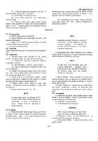
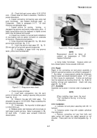
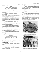
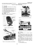
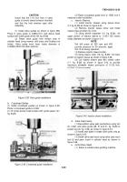
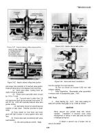
Install dial gage and holder (34, fig. B-28) as shown
in figure 321, and check crankshaft flange concentricity
as follows:
(1) Place chalk marks at position A, A’, B, and B’
as shown in (fig. 3-21).
(2) Check reading at B and B’. Total runout is not
to exceed 0.010 inch.
(3) Check reading at A and A’. Total runout is not
to exceed 0.010 inch.
(4) If flywheel housing bore is not within limits,
move as necessary to correct measurements.
CAUTION
Oil seal bore run-out must also
remain within limit of 0.005-inch.
e.
If both bores cannot be brought within limits, the
flywheel housing must be replaced.
f.
After measurements are brought within limits,
tighten capscrews alternately and evenly; make final
check after tightening. Tighten capscrews to 35 ft. lbs.
torque.
g.
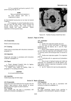
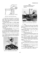
Check flywheel housing face as follows.
(1) Move dial gage-(fig. 3-21) and attachment to
housing face.
(2) Using a pinch bar wedged between a main
bearing cap and crankshaft throw, take up crankshaft
end clearance.
3-12
Back to Top

