TM-9-2815-213-34 - Page 37 of 192
*TM 9-2815-213-34
NOTE
If new rods are used,
be sure caps and
rods have number stamped on them
before caps are removed.
Caps are not
interchangeable.
d
.
Rotate engine to a vertical position on the engine
stand.
Rotate crankshaft to position crank throw for
cylinder being assembled at bottom center.
CAUTION
Ring breakage will result from improper
use of ring compressor.
If band type
compressor is used,
make certain inner
band does not slip down and bend
piston.
e
. With ring compressor in place,
insert piston
and rod assembly in the cylinder.
Position numbered
side of rod toward outside of block
.
CAUTION
Pistons are marked to indicate which
side is to be assembled to "Out" exhaust
side.
f
.
Push piston assembly through ring compressor
until rings seat in cylinder sleeve.
g
.
Moving to bottom of block,
grasp piston and rod
assembly by rod bolts and pull down to rod journal.
Leave piston assembly a short distance from actual
seating.
h
. Coat rod bearing shell with GAA next to the
crankshaft.
i
.
Roll rod bearing shell into rod.
Shell locking tang
must fit in milled recess.
j
.
Coat
lower shell crankshaft bore with hit
pressure grease,
and seat in rod cap.
k
.
Position rod cap over bolts that numbered side
of cap mates with numbered side of rod.
l
.
Lubricate bolt and nut threads and lock plates
with clean OE-10 lubricating oil.
Install lockplate and
nuts to bolts,
tighten nuts as outlined below.
(1)
Tighten both nuts 55 to 66 foot-pounds
torque.
(2)
Tighten both nuts 105 to 115 foot pounds
torque.
(3)
Loosen both nuts completely to remove all
tension.
(4)
Tighten both nuts to 30 to 32 foot- pounds
torque.
(5)
Tighten both nuts to 60 to 65 foot-pounds
torque.
(6)
Advance both nuts to 60 degrees in 30
degrees increments.
m.
Follow steps a through I above,
install piston
and rod assembly opposite one just installed. Secure
rod to same crankshaft journal.
NOTE
Chamfered side of rod faces respective
crankshaft cheeks and square sides
face each other.
n
. Check rod for freedom of movement and
clearance.
(1)
Use hand pressure to move rod side-ways.
Tap lightly with soft hammer if necessary.
(2)
If rod is not free,
loosen cap and check for
dirt or burs.
Secure cap as described above.
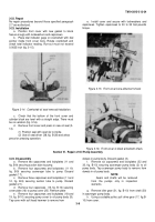
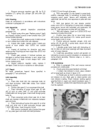
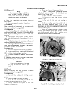
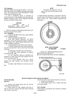
(3) Push rods apart. Check for 0.008 to 0.016 inch
clearance between rods with feeler gage (fig.
3-13).
o
.
Bend tangs on lockplates (fig.
3-13),
to
locknuts.
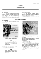
Figure 3-13.
Rod side clearance check.
Section V.
Repair of Front Cover
3-19.
Disassembly
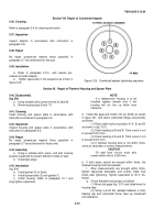
Using the front crankshaft oil seal driver (38,
fig. B-28)
and suitable arbor press remove oil seal as shown in
figure 3-14.
3-20.
Cleaning
Refer to paragraph 2-5 for cleaning instruction.
3-21.
Inspection
Refer to paragraph 2-6 for inspection procedures.
NOTE
Dowel replacement is not authorized.
If dowels are bent or damaged replace
the cover.
3-8
Back to Top

