TM-9-2815-213-34 - Page 39 of 192
C2, TM 9-2815-213-34
i.
Remove pressure regulator cap (28, fig. B-10
lockplate (27), spring (26), plunger (29) and shim (25)
from bore.
3-25. Cleaning
Clean all components in accordance with instructions
contained in paragraph 2-5
3-26. Inspection
a.
Refer
to
general
inspection
procedures
paragraph 2-6.
b.
Inspect pump drive gear. Replace pump if teeth
are chipped, cracked, scored or worn smaller than 2.397
inches outside diameter.
c.
Inspect drive shaft, replace pump if shafts scored
or worn smaller than 0.8740 inch outs diameter.
d.
Inspect idler shafts, replace pump if shafts are
scored or worn smaller than 0.8750 inch outside
diameter.
e.
Inspect all bushings for distortion and wear
replace pump if bushings are worn larger than .8750’ inch
inside diameter.
f.
Check gear pockets. If finished surfaces are
damaged or pocket inside diameter is worn larger than
2.4105 inches or if depth is worn deeper than 1.252
inches, replace pump.
g.
Inspect pressure regulator valve, replace if
damaged. Check for burs or scratches on slide plunger.
3-27. Repair
No repair procedures beyond those specified in
paragraph 2-7 are authorized.
3-28. Assembly
(fig. B-10)
a.
Press idler shaft (30) into scavenger body (2)
until shaft protrudes 1.935/1.965 inches from bottom
surface to pocket.
b.
Position idler gear (31) on scavenger idler shaft
c.
Press lubricating oil pump driven gear (6) with
drill oil hole on main shaft (7) until shaft protrudes
0.590/0.620 inch through gear. Insert shaft through pump
body (9).
d.
Press scavenger pump driven gear (6) on main
shaft and maintain 0.002/0.004 inch clearance between
gear and body.
e.
Press lubricating oil pump drive gear (6) on drive
shaft until drive end of shaft protrudes through gear
1.455/1.485 inches. Insert long end of shaft.
f.
With convex (numbered) side of pump drive gear
(17) up, press gear onto shaft until shaft protrudes
0.185/0.215 inch through drive gear.
g.
With new gasket (3) over dowels in pump body,
position scavenger body to lubricating oil pump body,
engaging pump gears. Secure with lockplates and
capscrews (32 and 33), lock capscrews in plate with lock
tangs.
h.
With new gasket (13) over dowels, position
pump cover (20) to lubricating oil pump body, engaging
pump gears; secure with lockplates and capscrews (18
and 19). Lock capscrews in place with lock tangs.
i.
With dial indicator, check for 0.0035/0.0075 inch
clearance of pump drive shaft.
j.
Position cover plate (16) on cover body secure
with socket head capscrews (15). Center punch around
screw heads to lock in cover.
k.
Position pressure regulator plunger, shim and
spring (25, 26 and 29) in pump body, secure with cap
and lockplate (27 and 28).
l.
Lubricate pump body freely with lubricating oil,
OE-10, drain oil, and cover openings with tape to prevent
entry of foreign material.
m. Install tube assemblies (suction and aerator) on
lubricating oil pump to permit installation of complete unit
during engine assembly. Reverse steps a., b., and c.,
paragraph 3-24.
3-29. installation
a.
Refer to paragraph 2-llm, and reverse removal
procedures to install pump.
b.
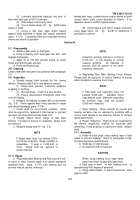
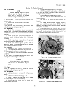
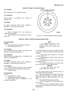
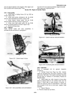
Check pump drive gear backlash as follows:
(1) Attach dial indicator to block, place indicator
arm on gear teeth as shown in figure 3-19.
(2) Rotate gear by hand to advance position and
set indicator at zero. Back gear to retard position and
note indicator reading. Check indicator reading against
specified limits in repair and rebuild standards (para. 3-
181). If reading is outside limits specified pump gear train
must be replaced.
Figure 3-17. Drive gear backlash check.
3-10
Back to Top

