TM-9-2815-213-34 - Page 40 of 192
•TM 9-2815-213-34
Section VII.
Repair of Camshaft
3-30. Disassembly
NOTE
Remove camshaft gear only if thrust
plate or gear is chipped, cracked or
visibly worn. If necessary to facilitate
removal, heat gear to 400 degrees F.
a.
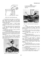
Place shaft in a suitable press between blocks and
press off gear.
b.
Remove key and thrust plate. Discard key.
3-31. Cleaning
Clean camshaft and components in accordance with
instructions contained in paragraph 2-5
3-32. Inspection
a.
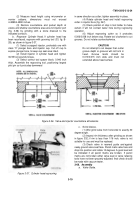
Check shaft journals and injector lobes against
specified limits in repair and rebuild standards paragraph
3-180. Replace shaft if any measurement is outside limits
specified.
b.
Check thrust plate against specified limits in
repair and rebuild standards, replace plate if limits are
exceeded.
c.
Visibly inspect gear in accordance with general
inspection procedures, paragraph 2-6
d.
Check gear diameter against specified limits in
repair and rebuild standards paragraph 3-180 Replace
gear if limits specified are exceeded
3-33. Assembly
a.
Install key in place, red tip to rear of camshaft.
b.
Coat camshaft thrust bearing with lubricating oil
OE10 and place thrust bearing on camshaft.
c.
Coat gear hub area on camshaft with lubricating
oil OE-10.
d.
Heat gear to 400 degrees Fahrenheit in oven or with
heating torch and press gear
onto shaft
CAUTION
When using heating torch, heat gear
hub only. Do not direct flame at gear
teeth.
3-34. Repair
Repair of camshaft and gear is limited to general
procedures outlined in paragraph 2-7.
3-35. Installation
a.
Lubricate lobes and journals with high pressure
grease.
b.
Install camshaft in the block (fig. 2-24).
c.
Index "0" mark on camshaft gear with “O” mark
on crankshaft gear to insure correct timing.
d.
Secure camshaft thrust plate to block with
lockplates and capscrews.
e.
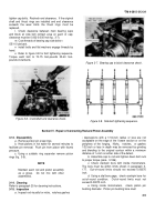
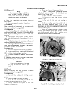
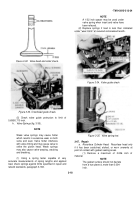
Check camshaft and clearance as follows:
(1) With a suitable holder attach a dial indicator
to the block, as shown in figure 3-18, with indicator arm
resting on face of gear teeth.
(2) Push and pull on shaft several times.
(3) Push shaft in until shaft bottoms and set
indicator to zero.
(4) Pull out oil shaft and note reading on
indicator.
(5) Check reading against specified limits in
repair and rebuild standards (para. 3-180). If end
clearance is not within limits specified remove camshaft
and replace thrust plate.
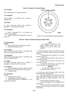
f.
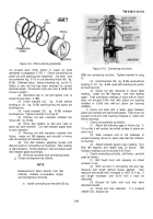
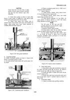
Attach dial indicator as shown in figure 3-19 and
measure gear backlash against limits specified in repair
and rebuild standards (para. 3-180). If backlash is not
within specified limits replace camshaft gear.
Figure 3-18.
Camshaft end play check.
Figure 3-19.
Crankshaft gear backlash check.
3-11
Back to Top

