TM-9-2815-213-34 - Page 43 of 192
•TM 9-2815-213-34
3-56. Assembly
Assemble flywheel and ring gear as follows:
a. If an oven
with a heat control is not available, heat gear with heating
torch, (not a cutting torch) from inside diameter so heat
travels outward towards the teeth.
b.
Use a Tempilstick crayon or equivalent to
determine amount of heat applied. Stroke gear with 600
degrees Fahrenheit crayon. At 600 degrees Fahrenheit
the crayon will leave a liquid smear.
CAUTION
Overheating
gear
to
temperatures
above
600
degrees
Fahrenheit will soften gear metal.
c.
Place the ring gear on flywheel and quickly drive onto
flywheel until gear is firmly seated.
3-57.
Installation
a.
Install two 5/8-18x6 inches long, guide headless
studs in crankshaft flange.
b.
Position flywheel over guide studs.
c.
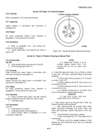
Insert eight flywheel capscrews, and tighten
alternately to 50 to 60 foot-pounds torque in sequence
shown in figure 3-22. Tighten flywheel capscrews to final
torque of 200/205 foot-pounds.
d.
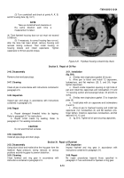
Check flywheel bore and clutch face as follows:
(1) Attach indicator and check pilot bearing bore
and drive ring pilot bore. Total run-out must not exceed
0.004 inch.
(2) Shift gage to indicate clutch mounting face.
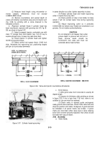
(3) Chalk four marks equidistant on flywheel
circumference (fig. 3-23).
(4) Turn crankshaft, taking up crankshaft end
clearance as chalk marks aline with indicator Run-out
must not exceed 0.005 inch.
(5) If run-out exceeds 0.005 inch, remove
flywheel and clean flywheel and crankshaft mating
surfaces.
(6) Again install flywheel and recheck bore and
face.
NOTE
Crankshaft end clearance must be
kept to rear limit while the above check
is made.
(7) Tighten flywheel capscrews to a final 200 to 205 foot-
pounds torque in 50 foot-pound increments in sequence
shown in figure 3-22.
Secure flywheel capscrews with
locking wire.
NOTE:
USE LOCKWIRE
AS REQUIRED
AT 40263
Figure 3-22.
Flywheel tightening sequence.
A
-BORE .004 INCH (RUN OUT)
B
-CLUTCH MOUNTING FACE .005 INCH (WOBBLE)
Section XII. Repair of Valve and Injector Tapplets
3-58. Disassembly
(fig. B-6).
a.
Remove and discard spring clips (31 and 35)
from tappet body (25 and 33).
b.
Place 0.006 inch shim between body side of
roller (27 and 29) to prevent sprit back when removing
roller. Press on end of pin
(26 and 32) that is not secured by lockwire to remove pin.
c.
Discard pin and lockwire.
d.
Press bearing sleeve (27) or injector roller (29)
from injector tappet.
3-59.
Cleaning
Clean tappets in accordance with instructions contained
in paragraph 2-5.
3-14
Back to Top

