TM-9-2815-213-34 - Page 45 of 192
•TM 9-2815-213-34
and are placed between valve tappets. Aline tappet and
lock in position with retainer plate. There
must be 0.010 inch clearance between tappet and plate
when capscrew is tightened down.
Section XIII.
Repair of Cylinder Heads
3-64.
Disassembly
a
.
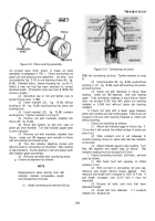
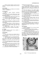
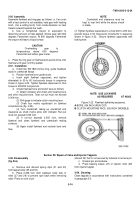
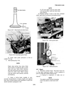
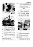
Install head in holding fixture (25, fig. B-28 as
shown in figure 3-25.
b
.
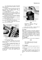
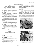
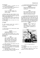
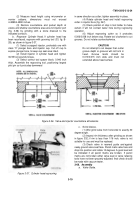
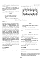
Using valve spring compressor (44, fig. B-28)
remove valve assemblies as shown in figure 3-26.
c.
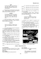
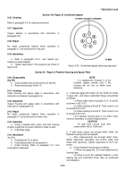
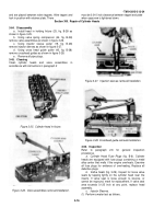
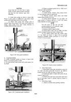
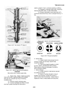
Using injector
sleeve puller (19, fig. B-28)
remove injector sleeves as shown in figure 3-27.
d
.
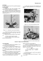
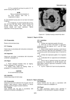
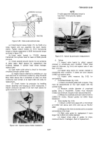
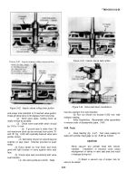
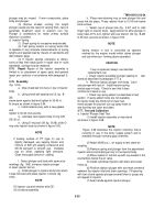
Using cross
head guide puller (43, fig. B-28)
remove crosshead guides as shown in figure 3-28.
e
.
Remove all pipe plugs.
3-45.
Cleaning
Clean cylinder heads and
valve
assemblies
in
accordance with instructions in paragraph 2
Figure 3-25.
Cylinder head in fixture.
Figure 3-26.
Valve assemblies-removal/installation.
Figure 3-27.
Injection sleeves-removal/installation.
Figure 3-28. Crosshead guide-removal/installation.
3-66.
Inspection
Refer
to
paragraph
2-6
for
general
inspection
procedures.
a.
Cylinder Head Fuse Plugs
(fig. B-6). Cylinder
heads are equipped with fuse plugs containing a metal
alloy center that melts if the engine overheats. Examine
all fuse plugs for evidence of overheating. Replace all
defective plugs.
b.
Valtve Seats
(fig. 3-29). Inspect for loose valve
seats by tapping lightly on the cylinder head near the
inserts. If valve seat is loose enough to bounce, or
cannot be reground, mark for replacement, If valve seat
area exceeds 0.125 inch at any point, replace head
assembly.
c.
Injector Sleeves.
(1)
Perform a water test as follows.
3-16
Back to Top

