TM-9-2815-213-34 - Page 34 of 192
*TM 9-2815-213-34
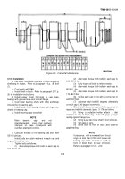
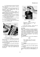
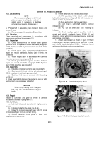
tighten cap bolts. Recheck end clearance.
If the original
shaft and thrust rings are installed and end clearance
exceeds the wear limits the thrust rings must be
replaced.
l
.
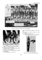
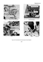
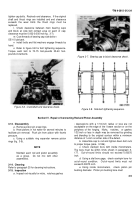
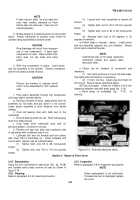
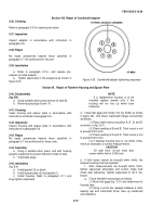
Check clearance between main bearing caps
and block at side bolt contact area on each of cap;
clearance must be 0.002-0.005-inch fig.
3-7).
m
. Coat threads of bearing cap side bolts v
OE-10 lubricant.
n
install bolts and flat washers engage threads by
hand.
o
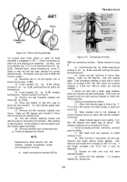
.
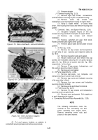
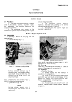
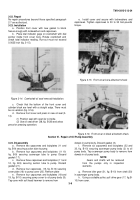
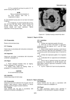
Refer to figure 3-8 for bolt tightening sequence.
Torque each bolt to 70-75 foot-pounds 35-40 foot-
pounds increments.
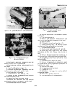
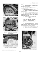
Figure 3-6.
Crankshaft end clearance check.
Figure 3-7.
Bearing cap to block clearance check.
Figure 3-8.
Side bolt tightening sequence.
Section IV.
Repair of Connecting Rod and Piston Assembly
3-13.
Disassembly
a
.
Remove piston pin snap rings.
b
.
Heat pistons in hot water for several minutes to
facilitate pin removal.
Push pin from piston with thumb
pressure.
c
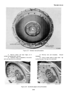
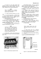
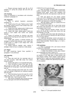
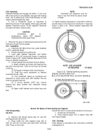
. Using a suitable ring expander remove piston
rings (fig.
3-9).
NOTE
Maintain each rod and piston assembly
as a group.
Do not mix with other
assemblies.
3-14.
Cleaning
Refer to paragraph 25 for cleaning instructions.
3-15.
Inspection
a
.
Inspect rod visually for nicks,
notches gashes
; depressions with a 1/16-inch radius or less are not
acceptable on the edge of the I beam section or on the
periphery of the forging.
Nicks,
notches,
or gashes
1/32-inch or less in depth may be removed by grinding
and blending to the original contour within a minimum
distance of ½ inch on either side of the defect.
b
.
Assemble cap to rod and tighten down bolt nuts
to proper torque (para.
3-186).
c
.
Check crankpin bore with inside micrometers.
The bore must be within limits shown in paragraph 3-
177.
Out-of-round limits should not exceed 0.00075
inch.
d
.
Using a dial bore gage,
check crankpin bore for
out-of-round condition. Out-of-round limits must not
exceed 0.00075 inch.
e
.
Using inside micrometers,
check piston pin
bushing diameter.
Piston pin bushing bore must
3-5
Back to Top

