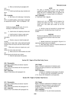
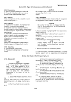
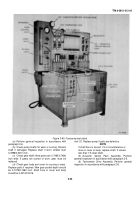
TM-9-2815-213-34 - Page 66 of 192
*TM 9-2815-213-34
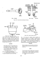
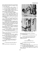
Figure 3-72. Air compressor drive gear timing mark.
(b)
Remove plate (16), packing (17), nylon washer
(18), diaphram (19), O-ring (20), body (21), and seal ring
(22).
(3)
Mainshaft Cover and Governor Assembly
(fig. B-
18).
(a)
Remove six capscrews, lockwashers, and plain
washers (33, 34, and 35) securing main shaft cover and
governor assembly to pump housing.
(b)
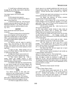
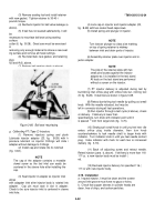
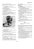
Using fuel pump governor weights puller (28, fig.
B-28), remove governor weights assembly (19) from
cover as shown in figure 3-75.
(c)
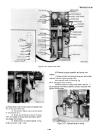
Remove retaining ring (30) from governor weight
carrier shaft (27).
(d)
Remove sleeve bushing (29) and drive shaft
gear (28).
(e)
Remove weight pivot pins (24) and hollow pin
shafts (25), supporting governor weights (26), and thrust
washers (20).
(f)
Remove weights, washers, compression spring
(21), flat shimming washers (22), and weight assist
plunger (23).
(g)
Remove capscrew (7), lockwasher (8), flat
washer (9), and hub (10) securing drive assembly to
cover.
NOTE
The hub is keyed to the shaft by key (18).
(h)
Remove tachometer drive gear (16),
3-37
Back to Top

