TM-9-1200-215-34-P - Page 62 of 266
TM 9–1200–215–34&P
2–27
2–18.
CPU CCA MAINTENANCE INSTRUCTIONS CONTINUED
b.
INSTALLATION
CAUTION
ESD SENSITIVE
The ACU contains ESD sensitive
components. Wear a protective
ESD wrist strap whenever handling
components. Failure to comply may
result in damage to equipment.
1.
Attach ESD grounding strap to wrist and ground
to ensure ESD protection.
CAUTION
When installing CPU CCA, ensure
that transistor on CCA clears spacer
assembly.
NOTE
Carefully position CPU CCA onto
backplane.
When installing CPU
CCA, connectors on card edge make
it necessary to tilt CCA slightly.
2.
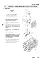
Position CPU CCA (13) in connectors J1 and J2
on backplane (21) in ACU housing.
Do not
secure to backplane at this time.
3.
Route five ribbon cables (22) between housing
and CPU CCA in the following sequence:
first
the cable that connects to J3, then J5, J6, J7,
and J9.
4.
Connect five ribbon cables (22) and mouse cable
J13 (23) to back of CPU CCA in the following
sequence:
J3, J9, J5, J6, J13, and J7.
5.
Connect SCSI cable connector (5) to CPU CCA
at J2 (6).
6.
Secure CPU CCA (13) to backplane (21) by
pushing down firmly on CCA.
NOTE
•
Use screw, lockwasher and flat
washer supplied with CPU CCA
when installing heatsink.
Discard
other hardware.
•
Ensure that hole in heatsink and
transistor are aligned with spacer
assembly before installing
hardware.
7.
Install circuit board heatsink (17) between
transistor and CPU CCA and insert screw (16)
into spacer assembly in ACU.
Torque screw to 5
in.–lb (0.6 N
S
m).
8.
Tighten screw (20) in Loktainer of CPU CCA.
5
6
13
21
13
17
16
20
21
22
22
23
J9
J2
J3
J6 J7
J13
J5
Back to Top


