TM-9-1200-215-34-P - Page 60 of 266
TM 9–1200–215–34&P
2–25
2–18.
CPU CCA MAINTENANCE INSTRUCTIONS CONTINUED
a.
REMOVAL CONTINUED
3.
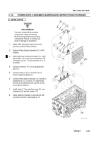
Disconnect SCSI cable connector (5) from
CPU CCA at J2 (6).
CAUTION
The connector panel assembly is
attached by cables to internal
components of ACU and cannot be
moved very far from housing without
putting strain on those cables.
Exercise caution when removing
bottom cover from ACU housing.
Failure to comply may result in
damage to equipment.
4.
Remove ACU connector panel (7) by removing
16 screws (8) and 16 flat washers (9).
Lift
connector panel off housing (10).
5.
Inspect EMI shielding gasket (11) in groove in
housing (10) for cuts, nicks, or signs of
stretching.
Discard EMI shielding gasket if
unserviceable.
6.
Disconnect Ethernet cable connector (12) from
CPU CCA (13).
7.
Loosen two captive screws (14) and
disconnect VGA cable connector (15) from
CPU CCA.
NOTE
Do not remove spacer assembly
from housing.
It is custom made to
ensure the CPU CCA is pressed
firmly against heatsink.
8.
Remove screw (16) and circuit board heatsink
(17) from spacer assembly in ACU.
9.
Remove screw (18) and flat washer (19) from
holddown of CPU CCA.
5
7
8
9
6
17
16
11
10
12
14
15
19
18
13
Back to Top


