TM-9-2320-273-34 - Page 475 of 801
TM 9-2320-273-34
(h)
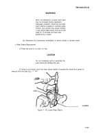
Place spider-center cam assembly on the driven clutch, indexing the teeth. Make sure
slot in the holdout-ring and spider-key are properly mated, as shown in figure 11-26.
Figure 11-26. A line Gaps in Holdout Rings with Spider Keys.
(i)
Place the other clutch holdout-ring assembly on the spider again, indexing the teeth,
and being sure again that the spider-key and holdout-ring slot are properly alined. Assemble the spring
over the clutch with larger diameter of spring against the clutch.
(j)
Place the other spring retainer over the other side gear splines (cup section up with the
retainer firmly seated against the side gear flange), and assemble the spring retainer and side gear over the
spring.
(k)
Mount the mating half of the case over the side gear and compress unit. Be sure the
side gear splines are completely indexed with the clutch splines. (See figure 11-17 for illustration of
complete assembly. )
(l)
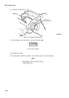
Hold the case halves together firmly, alining the punch marks (fig. 11-27) to be sure
the two case halves are properly mated. Start threading some of the case bolts but do not release hand
pressure until two or more bolts are drawn up enough to overcome the spring pressure.
Figure 11-27. Mount the Mating Case Halves.
11-29
Back to Top

