TM-9-2320-273-34 - Page 479 of 801
TM 9-2320-273-34
(3)
After obtaining a satisfactory tooth contact, the backlash can be altered within the limits of
0.005-0.015 in. (0.127-0.381 mm) for M915 forward rear axle and both rear axles on models M916
through M920. Use 0.008-0.020 in. (0.203-0.508 mm) for M915 rear rear axle gears to obtain a better
contact position relative to the length of the tooth.
(4)
A high backlash setting can be used to keep the contact from starting too close to the toe,
and a low backlash setting can be used to keep the contact from starting too far away from the toe.
(5)
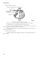
After correct tooth contact has been established, install adjusting nut cotter pins and
capscrews.
(6)
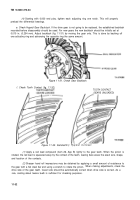
With adjustments properly made (pinion at correct depth and backlash set at 0,010 in.
(0.254 mm) the contacts in figure 11-32 will be procured. The area of contact favors the toe and is
centered between the top and bottom of the tooth.
(7)
After final adjustments, install cotter keys in adjusting nuts (fig. 11-30).
(8)
The hand-rolled pattern shown (gears unloaded), will result in a pattern centered in the
length of the tooth when the gears are under load, as shown (gears loaded). The loaded pattern will be
almost full length and the top of pattern will approach the top of the gear tooth.
(9)
The pattern on the coast side of teeth will appear the same width as the drive side shown
above; however, the overall length will be centered between the toe and heel of gear tooth,
After the
correct contacts, as shown, have been established with a backlash of 0.010 in. (0. 254 mm), open the
backlash to measure between 0.005-0.015 in. (0. 127-0.381 mm), if required.
(10) Set used
gear to have the tooth contacts to match wear patterns. Hand-rolled patterns of
used gears will be smaller in area and should be at the toe end of wear patterns.
(11)
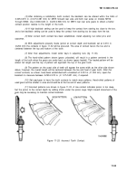
Incorrect patterns are shown in figure 11-33. A low contact indicates pinion is too deep.
Set the pinion to the correct depth by adding shims under the pinion cage. Slight inward movement of the
gear may be necessary to maintain correct backlash.
Figure 11-33. Incorrect Tooth Contact.
11-33
Back to Top

