TM-9-2320-283-13-P - Page 186 of 400
TM 9-2320-283-13&P
0022
0022-6
1
2
3
4
2
5
6
7
8
9
10
INSTALLATION, SENSOR, REAR-REAR AXLE – CONTINUED
5.
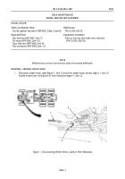
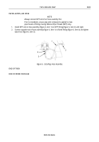
Connect harness brown wire (figure 8, item 5) to sensor cable white wire (figure 8, item 4) and harness
black wire (figure 8, item 1) to sensor cable black wire (figure 8, item 3) using two new wire connectors
(figure 8, item 2). Crimp and tape wire connectors (figure 8, item 2) with electrical tape.
6.
Route end of wheel sensor cable (figure 8, item 8) under frame rail (figure 8, item 10) and up behind
rear modulator mounting bracket (figure 8, item 6).
7.
Connect wheel sensor cable (figure 8, item 8) to rear wheel sensor harness (figure 8, item 9) located
inside frame rail adjacent to rear modulator (figure 8, item 7).
8.
Secure wheel sensor cable (figure 8, item 8) with additional tie straps as noted during removal.
Figure 8. Connecting Wheel Sensor at Rear-Rear Axle.
END OF TASK
INSTALLATION, SENSOR, FRONT AXLE
1.
Install clamp sleeve (figure 9, item 2) on hole (figure 9, item 3) in front spindle and brake spider (figure
9, item 4).
2.
Install wheel sensor (figure 9, item 1) on clamp sleeve (figure 9, item 2) and push wheel sensor
(figure 9, item 1) in until it contacts tone ring.
3.
Install split loom (figure 9, item 7) on cable (figure 9, item 5). Tape end of split loom (figure 9, item 7) to
cable (figure 7, item 5) with electrical tape.
4.
Secure split loom (figure 9, item 7) to camshaft bracket (figure 9, item 8) with two new tie straps (figure
9, item 6).
Back to Top

