TM-9-2320-283-13-P - Page 184 of 400
TM 9-2320-283-13&P
0022
0022-4
1
2
3
REMOVAL, SENSOR, REAR-REAR AXLE
–
CONTINUED
CAUTION
When removing wheel sensor from clamp sleeve, do not pull from
cable or damage to sensor may result.
5.
While holding end of wheel sensor (figure 5, item 1), pull and remove wheel sensor (figure 5, item 1)
from clamp sleeve (figure 5, item 2).
6.
Remove clamp sleeve (figure 5, item 2) from mounting bracket (figure 5, item 3).
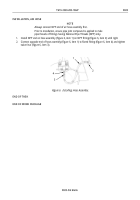
Figure 5. Wheel Sensor, Clamp Sleeve, and Mounting Bracket.
END OF TASK
NOTE
Wheel sensors on front and rear-rear axles are installed differently.
INSTALLATION, SENSOR, REAR-REAR AXLE
1.
Install clamp sleeve (figure 5, item 2) and wheel sensor (figure 5, item 1) on mounting bracket
(figure 5, item 3). Slide wheel sensor (figure 5, item 1) approximately halfway in clamp sleeve
(figure 5, item 2).
2.
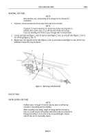
Route wheel sensor power cable (figure 6, item 1) through hole (figure 6, item 7) and install mounting
bracket (figure 6, item 5) on axle housing and brake spider (figure 6, item 4) with two bolts
(figure 6, item 6), washers (figure 6, item 3), and new locknuts (figure 6, item 2).
3.
Using screwdriver, push wheel sensor (figure 6, item 9) in until it contacts tone ring (figure 6, item 8).
Back to Top


