TM-9-2330-227-14-P - Page 116 of 576
TM 9-2330-227-14&P
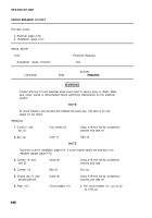
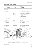
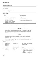
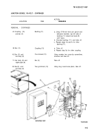
DOOR SWITCHES, 110-VOLT - CONTINUED
ACTION
LOCATION
ITEM
REMARKS
WARNIN G
Contact with live 110-volt electrical wires could result in serious injury or death. Make
sure power source is disconnected before performing maintenance on the electrical
system.
NOT E
Tag wires to aid in installation (page 4-4). Both door switches are removed and
installed the same way. This task is for one; repeat for the other.
REMOVAL
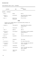
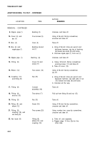
1.
2.
3.
4.
5.
6.
7.
8.
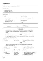
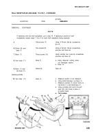
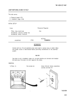
Cover (1) and
Four captive
Using 3/16-inch flat-tip screwdriver,
switch body (2)
screws (3)
unscrew.
Switch body (2)
Cover (1) and four
Take off.
captive screws (3)
Screws will stay with cover.
NOT E
Tag wires to aid in installation (page 4-4). If circuit marker bands are missing or not
readable, replace (page 4-73).
Three
Three contact
contacts (4)
screws (5) and
washers (6)
Three wires (8)
Switch body (2)
Three screws (10)
and van body (9)
Van body (9)
Switch body (2)
and plate (11)
Actuato r
Two screws (13)
and van body (9)
and Iockwashers (14)
Van body (9)
Actuator (12)
INSTALLATION
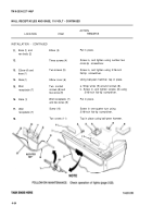
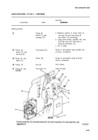
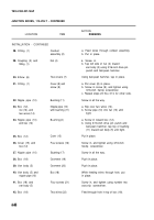
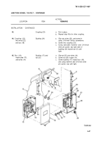
9.
Actuator (12)
4-38
a. Move insulator flap (7) aside.
b. Using 3/16-inch flat-tip screwdriver,
unscrew and take off.
Pull off.
Using number two cross-tip screwdriver,
unscrew and take off.
Take off, and separate.
a. Mark actuator (12) location for
installation.
b. Using number two cross-tip screw-
driver, unscrew and take off.
Take off.
Put in place.
Back to Top

