TM-9-2350-260-20-1-2 - Page 24 of 772
TM 9-2350-260-20-1-2
POWERPLANT REPLACEMENT (2A ENGINE) (Sheet 13 of 24)
47.
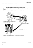
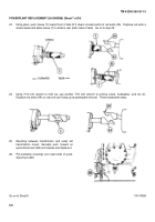
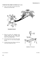
Lift powerplant in short, even lifts while checking that everything is clear.
48.
Move hoist rearward between lifts.
Rear of powerplant comes out first.
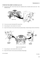
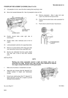
52.
Position second block under right side of
transmission.
53.
Position block under crankcase pad at front of
engine.
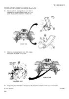
54.
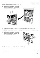
Lower powerplant carefully onto supporting blocks.
55.
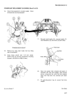
Remove six spring washers (AX) (three each side)
from transmission mounts (late model M60 only).
56.
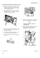
Remove two fabricated final drive guide shields
from each side of tank at final drive universal
joints.
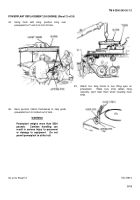
49.
Remove powerplant.
Move it away from tank.
Lower it to a few feet from ground level.
50.
Position three wooden blocks under powerplant for
support.
51.
Position block under left side of transmission.
INSTALLATION:
NOTE
Working area where powerplant mounts is tight and limited, make sure all
connections are ready.
Remove tools, rags, and any other materials not required
from engine compartment before installing powerplant.
1.
Make sure all surfaces in compartment are clean.
2.
Apply light coat of grease (Item 36, Appendix D) to
contact surfaces of engine and transmission
mounts.
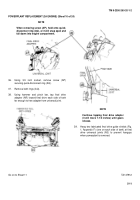
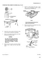
3.
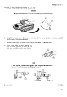
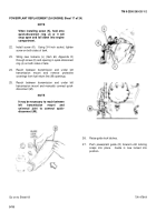
Using heavy masking tape (Item 57, Appendix D),
fasten generator air duct (A) to engine to prevent
damage during installation.
Go on to Sheet 14
TA147915
5-14
Back to Top

