TM-9-2350-260-20-1-2 - Page 30 of 772
TM 9-2350-260-20-1-2
POWERPLANT REPLACEMENT (2A ENGINE) (Sheet 19 of 24)
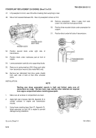
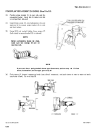
33.
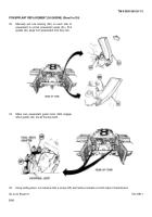
Position angle bracket (S) to rear side wall (by
powerplant guide).
Hang tab of bracket onto tab
on compartment side wall.
34.
Install three screws (T), new lockwashers (U), and
washers (V) to secure angle bracket (S) to side
wall (both sides).
35.
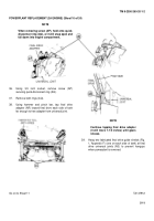
Using 9/16 inch socket, tighten three screws (T)
(both sides) to secure bracket (S) to side wall.
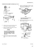
NOTE
Before connecting brake rod ends,
make sure two clamps (W) are on
each boot (X).
NOTE
If your tank has a spring loaded sleeve type disconnect, perform step
36.
If it has
screw, lockwasher, and nut type, go to step 37.
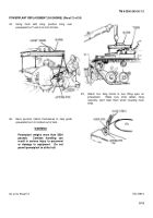
36.
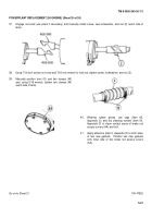
Push sleeve (Y) forward, engage rod ends (use pliers if necessary), and push sleeve to rear to retain rod ends
(each side of tank).
Go on to step 38.
Go on to Sheet 20
TA147921
5-20
Back to Top

