TM-9-2350-261-20-2 - Page 137 of 1008
TM 9-2350-261-20-2
REPLACE MASTER SWITCH PANEL ASSEMBLY (EARLY SLAVE
RECEPTACLE) (M577A2 AND M1068 ONLY)
0224 00
THIS WORK PACKAGE COVERS:
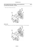
Removal (page 0224 00-1).
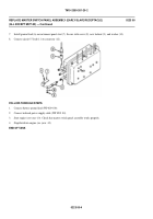
Installation (page 0224 00-5).
INITIAL SETUP:
Maintenance Level
Unit
Tools and Special Tools
General Mechanic’s Tool Kit (WP 0780 00, Item 29)
Materials/Parts
Grommet (11)
Lockwasher
Locknut (8)
Personnel Required
Unit Mechanic
Equipment Condition
Engine stopped (see your -10)
Carrier blocked (see your -10)
Battery ground lead disconnected (WP 0294 00)
REMOVAL
NOTE
Step 6 is for 200 amp generator system only. All other steps are common.
1.
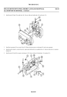
Remove eight locknuts (1), washers (2), and screws (3). Separate master switch panel assembly (4) from distribution
box (5). Discard locknuts.
2.
Disconnect wiring harness (6) leads (7), (8), and (9) from three circuit breakers (10), (11), and (12).
3.
Remove nut (16), washer (17), and circuit 49 lead (13) from bottom terminal on master switch (14).
022400-1
Back to Top


