TM-9-2815-205-34 - Page 153 of 596
TM 9-2815-205-34
3-10. AIR BOX HEATER HARDWARE REPLACEMENT (MODELS 5063-5299,5063-5395,
5063-5398, AND 5063-539F) (Cont)
d. Installation
(1)
(2)
(3)
(4)
(5)
(6)
(7)
(8)
3-28
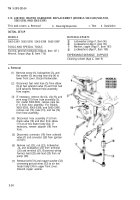
Loosely install support (47), two flat
washers (81), two Iockwashers (80), and
two screws (79) on upper front cover.
Loosely install bracket assembly (46),
screw (78), flat washer (77), Iockwasher
(76), and nut (75) on support (47).
Install two hardened washers (73) and
two screws (72) on bracket assembly (46)
into blower (74). Torque two screws (79)
to 46-50 Ib-ft (62-68 N
.
m), nut (75) to
30-35 Ib-ft (41-47 N-m), and screws (72)
to 55-60 Ib-ft (75-81 N
.
m).
For model 5063-5299:
(a) If removed, install pipe nipple (66)
and tee (62) in air inlet adapter (63).
Install adapter (64) and adapter (65)
into hose.
(b) Connect hose assembly 60) to
elbow (61) on air pump (30) and then
to tee (62) in air inlet elbow (63).
For
(a)
models 5063-5395 and 5063-539F:
If removed, install adapter (67), adapter (69), connector (70), and tee (71) into hose (68).
(b) Connect adapter (67) on hose
assembly (68) to elbow (61) on air
pump (30).
If removed, install elbow (51) (inlet port),
adapter (59), and elbow (6) (outlet port) to
solenoid valve (7).
Install solenoid valve (7), two Iockwashers
(58) and two screws (57) on bracket (56)
with fuel inlet facing right bank. Tighten
screws.
NOT E
For access to screws, loosen
nut on top of solenoid and ro-
tate coil housing. Rotate con-
nector toward right bank and
securely tighten nut after
bracket is installed.
Install solenoid valve bracket (56), two flat washers (55), two Iockwashers (54), and two screws
(53) on upper front cover. Torque screws to 30-35 Ib-ft (41-47 N
.
m).
Back to Top


