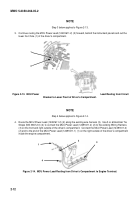
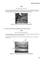
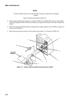
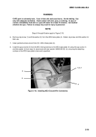
MWO-5-2350-262-35-2 - Page 11 of 33
MWO 5-2350-262-35-2
2
-
6
NOTE
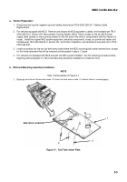
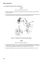
Steps 6 through 8 below apply to Figure 2-4.
6.
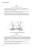
Attach four shock mounts (ME100-4-T) (6) to base bracket (12475721) (7) with eight lock washers
(12387272-41) (1), pan head machine screws (12387301-230) (2) and nuts (12387277-262) (5).
Hand-
tighten pan head screws until they are snug only.
7.
Insert threaded end of four cap screws (B181BH025C700N) (3) up through bottom of support bracket
(12475722) (4) with screw heads facing downward toward base bracket (7).
8.
Attach support bracket (4) to shock mounts (6) with four lock washers (12387272-42) (8) and pan head
machine screws (12387301-246) (9) keeping notch cutout (10) on support bracket (4) towards the end on
base bracket (7) with shorter mounting rails.
Hand-tighten pan head screws until they are snug only.
3
4
6
8
9
10
2
1
7
5
Figure 2-4.
Assembly of MCU Base and Support Bracket.
NOTE
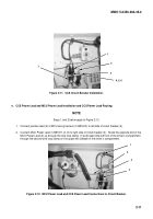
Steps 9 through 11 below apply to Figure 2-5.
9.
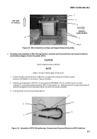
Install the assembled base and support brackets (4) on fuel tank armor plate with the three flat washers and
cap screws retained from step b.4. above and with one additional flat washer (12387279-14) (5), lock washer
(MS35338-103) (6), and cap screw (B1821BH038F100N) (7).
Ensure the end of the assembled base bracket
with the shorter mounting rails and the support bracket end with the notch cutout are both facing the left side
of vehicle.
10. Place MCU (B43020-1) (8) on assembled base and support bracket (4) with the electrical and coolant
umbilical connectors on the rear of the MCU facing the left side of the vehicle.
11. Install top bracket (12475723) (3) on top of the MCU (8) with four self-locking wing nuts (10917219) (1) on
cap screws (2).
Hand-tighten wing nuts until they are snug only.
Back to Top

