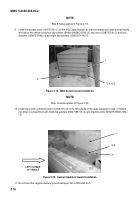
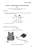
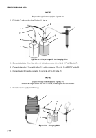
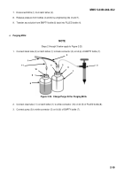
MWO-5-2350-262-35-2 - Page 15 of 33
MWO 5-2350-262-35-2
2
-
10
d.
Circuit Breaker Installation in Driver’s Compartment:
NOTE
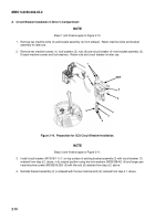
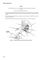
Steps 1 and 2 below apply to Figure 2-10.
1.
Remove two machine bolts (3) and bracket assembly (2) from sidewall.
Retain machine bolts and bracket
assembly for later use.
2.
Remove two machine screws (1), lock washers (5), nuts (6) and circuit breaker (4) from bracket assembly (2).
Discard machine screws and lock washers.
Retain nuts and circuit breaker for later use.
1
3
REF
2
3
4
5
5
6
Figure 2-10.
Preparation for CCS Circuit Breaker Installation.
NOTE
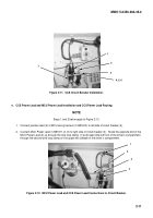
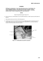
Steps 3 and 4 below apply to Figure 2-11.
3.
Install circuit breaker (M13516/1-1) (1) on top surface of existing bracket assembly (3) with circuit breaker (7),
retained from step d.2. above, in its original position using two lock washers (MS35338-42) (4) and longer pan
head machine screws (MS35206-250) (5) with the nuts (6) retained from step d.2. above.
4.
Reinstall bracket assembly (3) on sidewall with the two machine bolts (2) retained from step d.1. above.
Back to Top

