MWO-5-2350-262-35-2 - Page 13 of 33
MWO 5-2350-262-35-2
2
-
8
NOTE
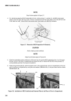
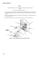
Step 4 below applies to Figure 2-7.
4.
For vehicles equipped with MCS preparation kit only, remove screw (1), washer (2), and MCS prep spacer
plate (4) from the upper left rear corner of driver’s compartment and the angle plate (3) from the left front side
of the radio box case.
Discard MCS prep spacer plate, angle plate, and attaching hardware.
2
3
1
4
HATCH COVER CLOSED
FOR ART CLARITY
Figure 2-7.
Removal of MCS Preparation Kit Brackets.
CAUTION
Avoid crimping coolant umbilical.
NOTE
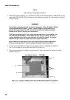
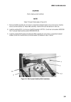
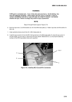
Steps 5 and 6 below apply to Figure 2-8.
5.
Slide the assembled coolant umbilical (2), MCU end first, through the MCS preparation hole (1) at the upper
left rear corner of the driver’s compartment and toward the rear of vehicle with the MCU wiring harness (3)
and assembled grommet (4) and grommet plate (5).
6.
Fasten the grommet plate (5) (with the angled corner in the upper left rear corner of compartment) to the rear
wall of the driver’s compartment (6) using two lock washers (MS35335-33) (7) and pan head machine screws
(MS35206-281) (8).
2
3
4, 5
1
5
6
7, 8
Figure 2-8.
Installation of MCU Umbilical and Grommet Plate at Left Rear of Driver’s Compartment.
Back to Top

