MWO-5-2350-262-35-2 - Page 12 of 33
MWO 5-2350-262-35-2
2-7
1
LEFT SIDE
OF VEHICLE
2
3
DRIVER’S
COMPARTMENT
5, 6, 7
4
8
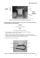
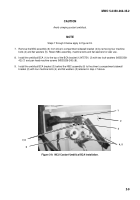
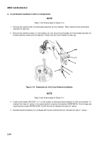
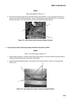
Figure 2-5.
MCU Installation on Base and Support Bracket Assembly.
c.
Assembly and Installation of MCU Wiring Harness, Grommet and Grommet Plate and Coolant Umbilical
and Umbilical Bypass Control Assembly (BCA):
CAUTION
Avoid crimping coolant umbilical.
NOTE
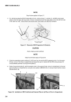
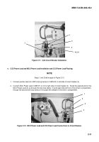
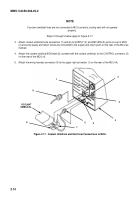
Steps 1 through 3 below apply to Figure 2-6.
1.
Position the MCU wiring harness (12491610) (2) against the outside of the MCU coolant
umbilical (LSF00664) (1) as shown in Figure 2-6 below.
2.
Slide the grommet plate (12475741) (4) and grommet (MS35489-114) (3) over MCU end of coolant
umbilical (1) and positive electrical lead of MCU wiring harness (2).
Slide grommet (3) and grommet plate (4)
towards the Bypass Control Assembly (BCA) (5) end of the coolant umbilical.
3.
Insert grommet (3) into the grommet plate (4).
3
4
2
5
1
Figure 2-6.
Assembly of MCU Wiring Harness, Grommet and Grommet Bracket on MCU Umbilical
.
Back to Top

