MWO-5-2350-262-35-2 - Page 16 of 33
MWO 5-2350-262-35-2
2-11
1
2
3
7
4, 5, 6
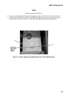
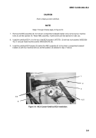
Figure 2-11.
CCS Circuit Breaker Installation.
e.
CCS Power Lead and MCU Power Lead Installation and CCS Power Lead Routing:
NOTE
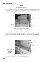
Steps 1 and 2 below apply to Figure 2-12.
1.
Connect positive lead (2) of MCU wiring harness (12491610) to left side of circuit breaker (4).
2.
Connect MCU Power Lead (12491611-2) (3) to right side of circuit breaker (4).
Route the opposite end of the
MCU Power Lead (3) up through the wire loop clamp (1) and toward the left front of the driver’s compartment
through the second wire loop clamp on the upper left sidewall of the driver’s compartment.
2
1
3
4
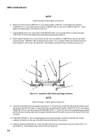
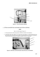
Figure 2-12.
MCU Power Lead and CCS Power Lead Connections to Circuit Breaker.
Back to Top

