TM-9-1200-215-34-P - Page 103 of 266
TM 9–1200–215–34&P
3–12
3–14.
ELECTROLUMINESCENT PANEL MAINTENANCE INSTRUCTIONS CONTINUED
b.
INSTALLATION CONTINUED
3.
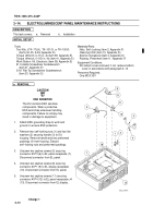
Clean filter glass (17) using alcohol and cloth.
Place filter glass into position in DU housing.
NOTE
Four hex head screws marked “A”
on illustration require two washers
each.
4.
Refer to illustration for proper placement and
place EL panel (16) into position in DU
housing. Align screw holes and secure to
housing with eight hex head screws (14) and
12 flat washers (15). Torque eight screws (14)
to 11
"
1 in.–lb (1.2
"
.1 N
S
m).
5.
Connect connector A1P4 (12) to EL panel
receptacle J4 (13). Secure connector by
torquing two captive screws (11) to
5.5
"
.5 in.–lb (.6
"
.1 N
S
m).
6.
Connect connector A1P1 (9) to EL display
receptacle (10). Secure connector by torquing
two captive screws (8) to 5.5
"
.5 in.–lb
(.6
"
.1 N
S
m).
7.
Connect connector A1P3 (6) to EL panel
receptacle (7). Secure connector by torquing
two captive screws (5) to 3
"
.2 in.–lb
(.34
"
.02 N
S
m).
8.
Insert handle (3) with two new preformed
packings (4) through holes in DU housing and
secure with two flat washers (2) and two new
self–locking nuts (1). Torque handle nuts to
140
"
.5 in.–lb (15.8
"
.1 N
S
m).
9.
Install DU bottom cover following procedure
outlined in paragraph 3–13.
1
2
3
A
A
A
A
17
15
14
7
6
5
10
9
8
11
12
14
15
16
13
4
Back to Top


