TM-9-1200-215-34-P - Page 111 of 266
TM 9–1200–215–34&P
3–20
3–18.
SERIAL CABLE ASSEMBLY MAINTENANCE INSTRUCTIONS
DESCRIPTION
This task covers:
a.
Removal
b.
Installation
INITIAL SETUP
Tools:
Tool Kits, JTK–17LAL, TK–101/G, or TK–105/G
(items 34, 35, & 36, Appendix E)
Torque Wrench, 0–150 in.–lb (item 41, Appendix E)
Torque Wrench, 0–15 in.–lb (item 39, Appendix E)
2” x 3/4” Drive Socket (item 19, Appendix E)
3/16” Flat Tip Screwdriver Socketwrench
(item 23, Appendix E)
Work Station Kit, Electronic (item 38, Appendix E)
1/2” x 3/4” Socket Adapter (item 1, Appendix E)
3/8” x 1/2” Socket Adapter (item 2, Appendix E)
Materials/Parts:
Lockwasher (item 1, Appendix F)
Equipment Conditions:
Switch panel removed; if not, remove bottom cover
in accordance with paragraph 3–13
Personnel Required:
One MOS 35Y
a.
REMOVAL
CAUTION
ESD SENSITIVE
The DU contains ESD sensitive
components. Wear a protective
ESD wrist strap whenever handling
components. Failure to comply may
result in damage to equipment.
1.
Attach ESD grounding strap to wrist and
ground, to ensure ESD protection.
2.
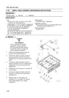
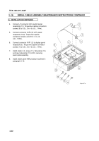
Unscrew two captive connector screws (4)
securing connector A1P4 (5) to EL panel
receptacle (6). Disconnect connector from EL
panel.
3.
Unscrew two captive connector screws (1)
securing connector A1P1 (2) to display panel
receptacle (3). Disconnect connector from
display panel.
4.
Remove jam nut (7) securing J1 connector (8)
to DU housing.
5.
Unscrew two captive connector screws (9)
securing J1 connector (8) to switch panel
receptacle (10).
6.
Remove screw (11), flat washer (12),
lockwasher (13), and clamp (14) securing
serial cable assembly to DU. Discard
lockwashers.
8
9
7
10
14
12
13
11
6
3
4
5
1
2
Back to Top

