TM-9-2320-283-13-P - Page 126 of 400
0018-24
TM 9-2320-283-13&P
0018
1
2
3
4
5
6
7
8
9
10
11
12
REMOVAL OF ITEMS FOR ACCESS OR REUSE – CONTINUED
NOTE
One bolt and washer, adapter, tee, and two elbows removed from
front axle ratio valve will be reused for installation of front bulkhead
union and air block bracket.
14.
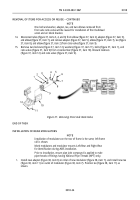
Disconnect tubes (figure 37, items 3, 4, and 6) from elbow (figure 37, item 2), adapter (figure 37, item 5),
and elbow (figure 37, item 7), and remove adapter (figure 37, item 5), elbow (figure 37, item 7), tee (figure
37, item 8), and elbow (figure 37, item 2) from ratio valve (figure 37, item 9).
15.
Remove two locknuts (figure 37, item 12), washers (figure 37, item 11), bolts (figure 37, item 1), and
ratio valve (figure 37, item 9) from crossmember (figure 37, item 10). Discard locknuts
(figure 37, item 12) and ratio valve (figure 37, item 9).
Figure 37. Removing Front Axle Ratio Valve.
END OF TASK
INSTALLATION OF REAR MODULATORS
NOTE
Installation of modulators on the rear of frame is the same; left frame
rail is shown.
Mark modulators and modulator mounts Left-Rear and Right-Rear
for identification during ABS installation.
Prior to installation, ensure pipe joint compound is applied to male
pipe threads of fittings having National Pipe Threads (NPT) only.
1.
Install new adapter (figure 38, item 6) on inlet of new modulator (figure 38, item 7), and install new tee
(figure 38, item 11) on outlet of modulator (figure 38, item 7). Position tee (figure 38, item 11) as
shown.
Back to Top


