TM-9-2320-283-13-P - Page 127 of 400
0018-25
TM 9-2320-283-13&P
0018
1
2 (32-3102)
3 (W348705)
4 (W373805)
5 (001-020-19-33)
(001-020-19-34)
6 (W1468X10)
7 (BW801481)
8 (W373805)
9 (W380524)
10 (W1480X10)
11 (W3750X8)
12 (W1468X10)
13
INSTALLATION OF REAR MODULATORS – CONTINUED
2.
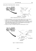
Install new adapter (figure 38, item 12) and new elbow (figure 38, item 10) on tee (figure 38, item 11).
Position elbow (figure 38, item 10) as shown.
3.
Install modulator (figure 38, item 7) on new driver-side modulator mount (figure 38, item 5) with two
new washers (figure 38, item 8), new bolts (figure 38, item 9), new washers
(figure 38, item 4), and new locknuts (figure 38, item 3).
NOTE
Modulator mounts are mounted on frame rails with bolts removed
from suspension components. Bolt heads shall be installed against
modulator brackets.
Prior to installing rear modulator brackets on frame rails, bend
existing loop clamp in toward frame rail for clearance.
4.
Install driver-side modulator mount (figure 38, item 5) on left frame rail (figure 38, item 1) with two
bolts (figure 38, item 13) and new locknuts (figure 38, item 2).
5.
Perform steps 1 through 4 for installation of opposite new modulator (figure 38, item 7) on right frame
rail.
Figure 38. Installing Rear Modulators.
END OF TASK
Back to Top


