TM-9-2320-283-13-P - Page 128 of 400
0018-26
TM 9-2320-283-13&P
0018
1
2
3
4
INSTALLATION OF FRONT MODULATORS
NOTE
Installation of modulators on front of frame is the same; left frame
rail shown.
Mark modulators Left-Front and Right-Front for identification during
ABS installation.
Prior to installation, ensure pipe joint compound is applied to male
pipe threads of fittings having National Pipe Threads (NPT) only.
It may be necessary to remove tape to access air tubes routed at left
frame rail.
1.
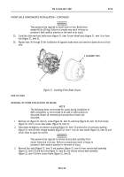
Working from inside left frame rail (figure 39, item 4) at front of truck, measure and cut tube
(figure 39, item 3) 4-1/2 in. (114 mm) from elbow (figure 39, item 1), and remove 4-1/2 in.
(114 mm) tube (figure 39, item 2) from elbow (figure 39, item 1). Retain both pieces of tubing
for installation.
Figure 39. Cutting Existing Front Brake Tube for Reuse.
2.
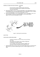
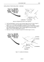
Install new adapter (figure 40, item 5) on outlet of new modulator (figure 40, item 6), and install
4-1/2 in. (114 mm) tube (figure 40, item 4) on adapter (figure 40, item 5).
3.
Hold modulator (figure 40, item 6) up to outside left frame rail (figure 40, item 3) at front of truck so
that end of 4-1/2 in. (114 mm) tube (figure 40, item 4) contacts brake hose (figure 40, item 2). With
modulator (figure 40, item 6) and tube (figure 40, item 4) level with frame rail (figure 40, item 3), mark
location of modulator mounting holes on frame rail (figure 40, item 3).
4.
Using punch and 5/16 in. (8 mm) drill bit, locate and drill two holes (figure 40, item 1) in left frame rail
(figure 40, item 3) as marked in step 3.
Back to Top


