TM-9-2320-283-13-P - Page 131 of 400
0018-29
TM 9-2320-283-13&P
0018
1
2
3
4
5
1
2
3 (PHPFT-10BGRN100)
4 (W1480X10)
5
6
3 (PHPFT-10BGRN100)
INSTALLATION OF ABS AIR LINES
NOTE
Plastic air line tubing is connected to fittings with a brass ferrule
supplied with new fittings or replacement ferrule.
When installing air line tubing, length of tubing shall be trimmed so
there is a small amount of looseness when both ends are connected to
fittings and tubing is not so short it has to be pulled tight.
Prior to installation, ensure pipe joint compound is applied to male
pipe threads of fittings having National Pipe Threads (NPT) only.
1.
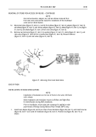
Remove tube (figure 44, item 4) from right adapter (figure 44, item 3) on relay valve (figure 44, item 2),
and remove tube (figure 44, item 5) and left adapter (figure 44, item 1) from relay valve (figure 44, item 2).
Discard tubes (figure 44, items 4 and 5).
Figure 44. Disconnecting Tubing from Relay Valve.
2.
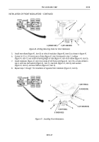
Install new elbow (figure 45, item 4) on relay valve (figure 45, item 1) pointing approximately at
5 o’clock position.
3.
Cut new 5/8 in. (16 mm) green tube (figure 45, item 3) to 29 1/2 in. (75 cm) in length, connect tube
(figure 45, item 3) to adapter (figure 45, item 2), and connect opposite end of tube (figure 45, item 3) to
adapter (figure 45, item 5) on right-rear modulator (figure 45, item 6).
Figure 45. Connecting Tube to Relay Valve and Right-Rear Modulator.
Back to Top


