TM-9-2320-283-13-P - Page 138 of 400
0018-36
TM 9-2320-283-13&P
0018
1
2
3
4
5
INSTALLATION OF ABS AIR LINES – CONTINUED
30.
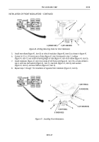
Disconnect tubes (figure 54, items 3 and 4) from adapter (figure 54, item 1) and elbow
(figure 54, item 2), located at front end of primary reservoir (figure 54, item 5).
Figure 54. Disconnecting Tubes from Primary Reservoir.
31.
Remove two nuts (figure 55, item 8) and screws (figure 55, item 4) from primary reservoir upper and
lower clamps (figure 55, items 5 and 7).
32.
Remove two nuts (figure 55, item 6) and upper clamps (figure 55, item 5) from right frame rail
(figure 55, item 9) and primary reservoir (figure 55, item 10).
NOTE
The 3/8 in. (9.5 mm) tube connected between primary reservoir and
the brake treadle valve is replaced with 5/8 in. (16 mm) tube.
33.
Slide primary reservoir (figure 55, item 10) back from crossmember, and disconnect tube
(figure 55, item 1) from elbow (figure 55, item 3) and tube (figure 55, item 2) from adapter
(figure 55, item 11). Cut off and discard end of 3/8 in. (9.5 mm) tube (figure 55, item 1).
Back to Top


