TM-9-2320-283-13-P - Page 147 of 400
0018-45
TM 9-2320-283-13&P
0018
1
1
2
3
*
4 (HDXGC3030)
2
1
2
3
4 (W3350X6)
5
1-3/4 in. (44 cm)
3 in. (76 mm)
4 (HDXGC3030)
3
*
INSTALLATION OF ABS AIR LINES - CONTINUED
65.
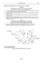
Thread new jamnut (figure 65, item 3) on pushrod (figure 65, item 2), and cut off pushrod
(figure 65, item 2) 1-3/4 in. (44 mm) from face of new spring brake chamber (figure 65, item 4).
Discard remaining piece of pushrod (figure 65, item 2).
66.
Install clevis (figure 65, item 1) on pushrod (figure 65, item 2) of spring brake chamber
(figure 65, item 4) until center of holes in clevis (figure 65, item 1) are 3 in. (76 mm) from face of
spring brake chamber (figure 65, item 4). Finger tighten jamnut (figure 65, item 3).
*
ITEM 3 SUPPLIED WITH ITEM 4
Figure 65. Shortening Pushrod and Installing Clevis.
67.
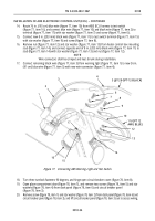
Install elbow (figure 66, item 5) on parking brake port (figure 66, item 1), and install new elbow
(figure 66, item 4) on service brake port (figure 66, item 3) of spring brake chamber (figure 66, item 2).
Figure 66. Installing Elbows on Spring Brake Chamber.
Back to Top


