TM-9-2320-283-13-P - Page 150 of 400
0018-48
TM 9-2320-283-13&P
0018
1
2 (91419871)
3
4 (W1468X8)
5
6 (54X8X8)
7 (W1468X8)
8
INSTALLATION OF ABS AIR LINES – CONTINUED
NOTE
The mountable tee and bolt previously removed from bracket at top
of forward-rear axle is reused in step 75.
75.
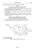
Install new elbow (figure 70, item 6) and two new adapters (figure 70, items 4 and 7) on mountable tee
(figure 70, item 8), and install mountable tee (figure 70, item 8) on top hole of rear-rear axle bracket
(figure 70, item 3) with new lockwasher (figure 70, item 2) and bolt (figure 70, item 1).
76.
Connect hose assembly (figure 70, item 5) to elbow (figure 70, item 6) on mountable tee
(figure 70, item 8).
Figure 70. Installing Mountable Tee on Rear-Rear Axle Bracket.
77.
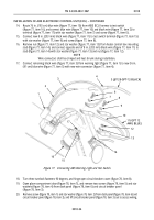
Measure and cut 9 in. (74 cm) new piece of 1/2 in. (13 mm) red bulk tubing (figure 71, item 4), and install
tube (figure 71, item 4) on mountable tee adapter (figure 71, item 3) and elbow (figure 71, item 5) on
parking brake port of spring brake chamber (figure 71, item 7) at left side of vehicle.
78.
Install new hose assembly (figure 71, item 8) on elbow (figure 71, item 6) at service brake port of spring
brake chamber (figure 71, item 7) and flared elbow (figure 71, item 1) at bulkhead
(figure 71, item 2).
NOTE
New 1/2 in. (13 mm) red tubing to be installed in step 79 will be cut
to 26 in. (66 cm) in length.
79.
Repeat steps 77 and 78 for installation of opposite tube (figure 71, item 4) and hose assembly
(figure 71, item 8) at right side of vehicle.
Back to Top


