TM-9-2320-283-13-P - Page 154 of 400
0018-52
TM 9-2320-283-13&P
0018
1 (44-608)
2
3
4
5 (44-6008)
6 (BW801877)
7
8
9
10
11
~
INSTALLATION OF ABS ELECTRONIC CONTROL UNIT (ECU) – CONTINUED
NOTE
Leave top left mounting hole in ECU open for connection of ground
wires in step 11.
6.
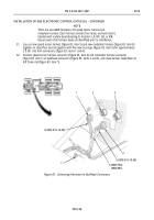
Install new ABS ECU (figure 75, item 6) on firewall (figure 75, item 11) with three new screws
(figure 75, item 5).
7.
Connect three black ground wires (figure 75, items 2, 3, and 4) to ECU (figure 75, item 6) and firewall
(figure 75, item 11) with new screw (figure 75, item 1).
8.
Connect harness connectors (figure 75, items 8 and 9) to ECU receptacles (figure 75, items 7 and 10).
Figure 75. Installing ABS ECU.
Back to Top


