TM-9-2320-283-13-P - Page 160 of 400
0018-58
TM 9-2320-283-13&P
0018
1
2
3
4
5 (000-019-19-26)
6 (W26764)
(W26681)
7
8 (000-019-19-25)
INSTALLATION OF ABS ELECTRONIC CONTROL UNIT (ECU) – CONTINUED
NOTE
There are two ABS harnesses: the speed sensor harness and
modulator harness. Each harness contains four leads, and each lead is
labeled with a white band denoting its location: LF, RF, LR, or RR.
Ensure ends of all harness leads are identified prior to installation.
31.
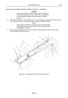
Lay out new speed sensor harness (figure 83, item 5) and new modulator harness (figure 83, item 8)
together on shop floor and tie together with five new tie straps (figure 83, item 6) for approximately
3 ft (91 cm) from connectors (figure 83, items 1 and 4).
32.
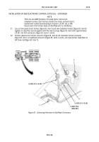
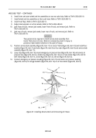
Connect speed sensor harness connector (figure 83, item 4) and modulator harness connector
(figure 83, item 1) to bulkhead connectors (figure 83, items 2 and 3), and route harness leads down to
left frame rail (figure 83, item 7).
Figure 83. Connecting Harnesses to Bulkhead Connectors.
Back to Top


